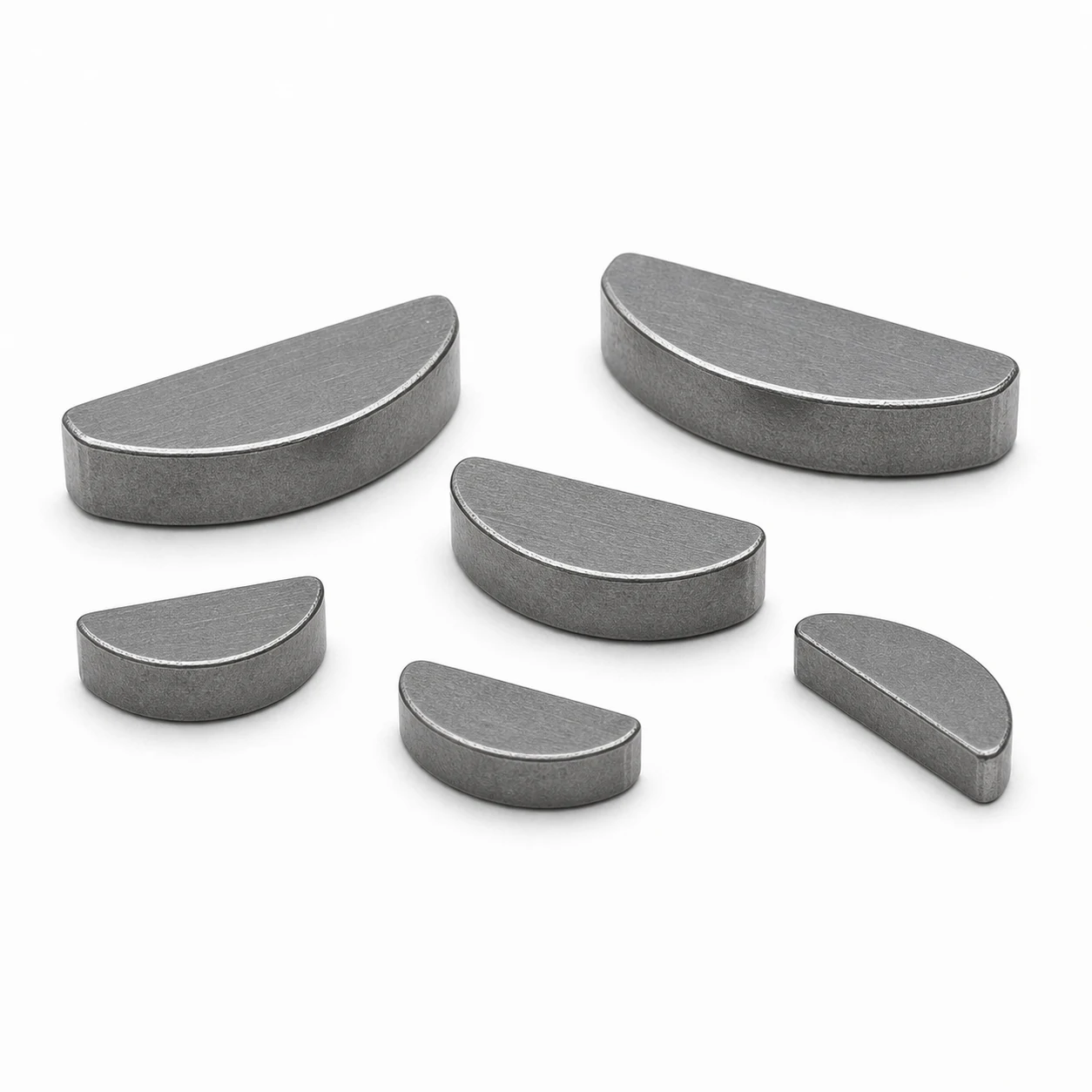
Woodruff Keys manufactured in A4 Stainless Steel (ISO 3506 group A4 (316 / 1.4401), commonly supplied A4-80) are dimensioned to DIN 6888. The sections below give the mechanical and physical properties of the grade, its behavior in corrosive and elevated-temperature service, and the full size table.
Why Choose A4 Stainless Steel for Woodruff Keys
Specified for marine, coastal and chemical applications. For woodruff keys, this matters when superior, including marine and chloride environments is the primary requirement.
Mechanical & Physical Properties
| Grade designation | ISO 3506 group A4 (316 / 1.4401), commonly supplied A4-80 |
|---|---|
| Magnetic response | Largely non-magnetic |
| Service temperature | approx. -200 °C to +400 °C, subject to the property class and the joint |
| Corrosion characteristic | Superior, including marine and chloride environments |
Corrosion Behavior in Service
A4 (316) adds 2–3% molybdenum to the A2 (304) composition, which dramatically improves resistance to chloride-pitting corrosion. For Woodruff Keys in marine, coastal, swimming-pool or food-processing environments, A4 is the default selection.
Comparable Grades
For Woodruff Keys, the alternative stainless grade is A2 (304). A2 (304) suits general indoor and outdoor service; A4 (316) adds molybdenum for marine and chloride environments. Where higher strength matters more than corrosion, switch to plated alloy-steel class 8.8 or 10.9.
Using Stainless Fasteners in Aluminum
Stainless steel is more noble than aluminum, so in the presence of an electrolyte — rain, condensation, salt spray — the aluminum becomes the anode and corrodes at the joint. The effect is driven by the area ratio: a small stainless fastener in a large aluminum section is normally acceptable, while a large stainless fastener in thin aluminum is not. Where the joint is wet, isolate the two metals with a coated or nylon washer and a sealant, or specify an aluminum or coated fastener instead.
Sizes of Woodruff Keys Available in A4 Stainless Steel
| Key width b (mm) | Disc diameter d (mm) | Key height h (mm) | Chord length l (mm) | Shaft groove depth t1 (mm) | Hub groove depth t2 (mm) | Reference standard |
|---|---|---|---|---|---|---|
| 1.0 | 4 | 1.4 | 3.7 | 1.0 | 0.6 | DIN 6888 / ISO 3912 |
| 1.5 | 4 | 1.4 | 3.7 | 1.0 | 0.6 | DIN 6888 / ISO 3912 |
| 2.0 | 5 | 1.8 | 4.7 | 1.4 | 0.6 | DIN 6888 / ISO 3912 |
| 2.0 | 6 | 2.6 | 5.7 | 2.0 | 0.8 | DIN 6888 / ISO 3912 |
| 2.5 | 7 | 3.0 | 6.8 | 2.3 | 1.0 | DIN 6888 / ISO 3912 |
| 3.0 | 7 | 3.0 | 6.8 | 2.3 | 1.0 | DIN 6888 / ISO 3912 |
| 3.0 | 9 | 4.0 | 8.8 | 3.2 | 1.0 | DIN 6888 / ISO 3912 |
| 3.0 | 10 | 4.5 | 9.8 | 3.5 | 1.2 | DIN 6888 / ISO 3912 |
| 4.0 | 9 | 4.0 | 8.8 | 3.2 | 1.0 | DIN 6888 / ISO 3912 |
| 4.0 | 10 | 4.5 | 9.8 | 3.5 | 1.2 | DIN 6888 / ISO 3912 |
| 4.0 | 13 | 6.0 | 12.7 | 5.0 | 1.4 | DIN 6888 / ISO 3912 |
| 5.0 | 10 | 4.5 | 9.8 | 3.5 | 1.2 | DIN 6888 / ISO 3912 |
| 5.0 | 13 | 6.0 | 12.7 | 5.0 | 1.4 | DIN 6888 / ISO 3912 |
| 5.0 | 16 | 7.5 | 15.7 | 6.3 | 1.4 | DIN 6888 / ISO 3912 |
| 6.0 | 13 | 6.0 | 12.7 | 5.0 | 1.4 | DIN 6888 / ISO 3912 |
| 6.0 | 16 | 7.5 | 15.7 | 6.3 | 1.4 | DIN 6888 / ISO 3912 |
| 6.0 | 19 | 9.0 | 18.6 | 7.5 | 1.8 | DIN 6888 / ISO 3912 |
| 8.0 | 19 | 9.0 | 18.6 | 7.5 | 1.8 | DIN 6888 / ISO 3912 |
| 8.0 | 22 | 11.0 | 21.6 | 9.3 | 1.8 | DIN 6888 / ISO 3912 |
| 10.0 | 22 | 11.0 | 21.6 | 9.3 | 1.8 | DIN 6888 / ISO 3912 |
| 10.0 | 25 | 13.0 | 24.5 | 11.0 | 2.3 | DIN 6888 / ISO 3912 |