Skip to content

Screws · ISO 4026 / ISO 4029 / DIN 913-916

M6 Socket Set Screws Dimensions & Specifications

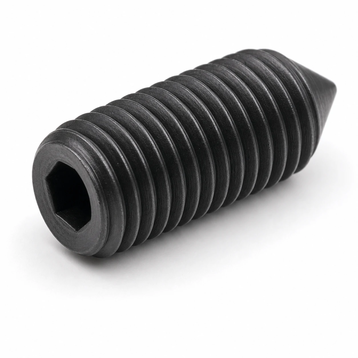
M6 Socket Set Screws Dimensions & Specifications reference image

Dimensional and assembly data for M6 Socket Set Screws to ISO 4026 / ISO 4029 / DIN 913-916. Includes head size and width across flats, clearance-hole and tapping-drill diameters, tightening torque per property class, and the sizes to step up or down to when the joint requires it.

M6 Dimensional Row (ISO 4026 / ISO 4029 / DIN 913-916)

SizePitch (mm)Hex socket s (mm)Engagement depth t min (mm)Point diameter dp (mm)End typeReference standard
M61.03.03.04.0Flat pointISO 4026 / DIN 913-916

Spanner & Drive for M6 Socket Set Screws

The hex socket for M6 Socket Set Screws is shown in the spec table — use the matching Allen / hex key (an ISO 2936 hex key set covers the full range). A T-handle Allen key gives the best feel for setting preload by feel; for production work use a torque-controlled driver.

Hole Sizes for M6

Coarse-thread pitch (ISO 724)1 mm
Through-hole / clearance (ISO 273 medium)6.6 mm
Tapping drill, coarse thread5 mm

Tightening Torque for M6

Class 8.8 (dry, ~µ 0.125)≈ 10 Nm
Class 10.9 (dry, ~µ 0.125)≈ 14 Nm
Class 12.9 (dry, ~µ 0.125)≈ 17 Nm

Indicative dry-joint values. Lubrication can lower the required torque by 15–25%. Always confirm against the joint design, especially when going up a strength class.

Proof Load & Strength for M6

Tensile stress area As (ISO 898-1)20.1 mm²
Proof load, class 8.812 kN
Proof load, class 10.917 kN
Proof load, class 12.919 kN
Min. ultimate tensile, class 8.816 kN

Proof load = stress area × proof stress per ISO 898-1. Design joints so the working preload stays below the proof load of the selected class.

Common Applications for M6 Socket Set Screws

M6 Socket Set Screws are commonly specified for machine assembly, general engineering, plant maintenance and OEM equipment.

Installation Tips for M6 Socket Set Screws

  • Use a quality Allen key fully seated in the socket — partial engagement is the most common cause of stripped sockets at this size.
  • For countersunk and button-head variants, chamfer the through-hole to seat the head flush without preloading the head/shank fillet.

When to Step Up or Down from M6

When the joint preload approaches the proof load of M6 class 8.8, step up to M8 class 8.8 (or move to M6 class 10.9). When the joint is over-specified, M5 often saves weight and cost without losing the safety margin.

Technical Drawing

Customize the parameters below — every spec field is editable, and the drawing redraws to match the values you choose. Changing the size will snap the other fields to that size's standard values; you can then override any individual value.

Sends the selected values to the quote form below.

Request a Quote

Adjust the parameters in the drawing above and click "Request this configuration" to send the exact specification straight to this form.

Request a Quotation

Specification
Business Information

Dimensions & Specifications (ISO 4026 / ISO 4029 / DIN 913-916)

SizePitch (mm)Hex socket s (mm)Engagement depth t min (mm)Point diameter dp (mm)End typeReference standard
M1.60.350.70.70.8Flat pointISO 4026 / DIN 913-916
M1.60.350.70.70.8Cone pointISO 4027 / DIN 913-916
M1.60.350.70.70.8Dog pointISO 4028 / DIN 913-916
M1.60.350.70.70.8Cup pointISO 4029 / DIN 913-916
M20.40.90.91.0Flat pointISO 4026 / DIN 913-916
M20.40.90.91.0Cone pointISO 4027 / DIN 913-916
M20.40.90.91.0Dog pointISO 4028 / DIN 913-916
M20.40.90.91.0Cup pointISO 4029 / DIN 913-916
M2.50.451.31.11.5Flat pointISO 4026 / DIN 913-916
M2.50.451.31.11.5Cone pointISO 4027 / DIN 913-916
M2.50.451.31.11.5Dog pointISO 4028 / DIN 913-916
M2.50.451.31.11.5Cup pointISO 4029 / DIN 913-916
M30.51.51.42.0Flat pointISO 4026 / DIN 913-916
M30.51.51.42.0Cone pointISO 4027 / DIN 913-916
M30.51.51.42.0Dog pointISO 4028 / DIN 913-916
M30.51.51.42.0Cup pointISO 4029 / DIN 913-916
M40.72.02.02.5Flat pointISO 4026 / DIN 913-916
M40.72.02.02.5Cone pointISO 4027 / DIN 913-916
M40.72.02.02.5Dog pointISO 4028 / DIN 913-916
M40.72.02.02.5Cup pointISO 4029 / DIN 913-916
M50.82.52.53.5Flat pointISO 4026 / DIN 913-916
M50.82.52.53.5Cone pointISO 4027 / DIN 913-916
M50.82.52.53.5Dog pointISO 4028 / DIN 913-916
M50.82.52.53.5Cup pointISO 4029 / DIN 913-916
M61.03.03.04.0Flat pointISO 4026 / DIN 913-916
M61.03.03.04.0Cone pointISO 4027 / DIN 913-916
M61.03.03.04.0Dog pointISO 4028 / DIN 913-916
M61.03.03.04.0Cup pointISO 4029 / DIN 913-916
M81.254.04.05.5Flat pointISO 4026 / DIN 913-916
M81.254.04.05.5Cone pointISO 4027 / DIN 913-916
M81.254.04.05.5Dog pointISO 4028 / DIN 913-916
M81.254.04.05.5Cup pointISO 4029 / DIN 913-916
M101.55.05.07.0Flat pointISO 4026 / DIN 913-916
M101.55.05.07.0Cone pointISO 4027 / DIN 913-916
M101.55.05.07.0Dog pointISO 4028 / DIN 913-916
M101.55.05.07.0Cup pointISO 4029 / DIN 913-916
M121.756.06.08.5Flat pointISO 4026 / DIN 913-916
M121.756.06.08.5Cone pointISO 4027 / DIN 913-916
M121.756.06.08.5Dog pointISO 4028 / DIN 913-916
M121.756.06.08.5Cup pointISO 4029 / DIN 913-916
M162.08.08.012.0Flat pointISO 4026 / DIN 913-916
M162.08.08.012.0Cone pointISO 4027 / DIN 913-916
M162.08.08.012.0Dog pointISO 4028 / DIN 913-916
M162.08.08.012.0Cup pointISO 4029 / DIN 913-916
M202.510.010.015.0Flat pointISO 4026 / DIN 913-916
M202.510.010.015.0Cone pointISO 4027 / DIN 913-916
M202.510.010.015.0Dog pointISO 4028 / DIN 913-916
M202.510.010.015.0Cup pointISO 4029 / DIN 913-916
M243.012.012.018.0Flat pointISO 4026 / DIN 913-916
M243.012.012.018.0Cone pointISO 4027 / DIN 913-916
M243.012.012.018.0Dog pointISO 4028 / DIN 913-916
M243.012.012.018.0Cup pointISO 4029 / DIN 913-916
M303.514.015.022.0Flat pointISO 4026 / DIN 913-916
M303.514.015.022.0Cone pointISO 4027 / DIN 913-916
M303.514.015.022.0Dog pointISO 4028 / DIN 913-916
M303.514.015.022.0Cup pointISO 4029 / DIN 913-916
M364.017.019.027.0Flat pointISO 4026 / DIN 913-916
M364.017.019.027.0Cone pointISO 4027 / DIN 913-916
M364.017.019.027.0Dog pointISO 4028 / DIN 913-916
M364.017.019.027.0Cup pointISO 4029 / DIN 913-916
M454.519.024.034.0Flat pointISO 4026 / DIN 913-916
M454.519.024.034.0Cone pointISO 4027 / DIN 913-916
M454.519.024.034.0Dog pointISO 4028 / DIN 913-916
M454.519.024.034.0Cup pointISO 4029 / DIN 913-916
M485.022.028.036.0Flat pointISO 4026 / DIN 913-916
M485.022.028.036.0Cone pointISO 4027 / DIN 913-916
M485.022.028.036.0Dog pointISO 4028 / DIN 913-916
M485.022.028.036.0Cup pointISO 4029 / DIN 913-916

Frequently Asked Questions

What torque do M6 class 8.8 Socket Set Screws take?

A dry M6 class 8.8 joint takes about 10 Nm (≈ 14 Nm for 10.9, ≈ 17 Nm for 12.9). Confirm against your joint design; lubrication reduces these values.

What clearance and tapping drill suit M6?

Use a 6.6 mm clearance hole (ISO 273 medium) for through-fixing, or a 5 mm tapping drill for a coarse M6 thread.

Which Allen key fits M6 Socket Set Screws?

The hex-socket size for each row of Socket Set Screws is shown in the spec table — use the matching Allen / hex key. An ISO 2936 set covers every size on this page.

How do I avoid stripping the socket on M6 Socket Set Screws?

Fully seat the key in the socket, choose ball-end keys only for low-torque finishing work, and prefer a T-handle key when feel matters. For production use a torque-controlled driver.

How do I request a quotation?

Use the technical drawing on this page to pick the exact configuration, then submit it with the quote form. We respond within one business day.