

Tap Drill Sizes (ISO 2306 (reference)) are a type of engineering reference used across industrial assembly. Below is the complete size table together with material, standard and application guidance.
About This Reference
This is an engineering reference table for tap drill sizes based on ISO 2306 (reference). Use it alongside our fastener catalog when selecting and specifying parts.
Reference Data (ISO 2306 (reference))
| Thread size | Pitch (mm) | Tap drill, standard d-P (mm) | Tap drill, reduced engagement (mm) | Description |
|---|---|---|---|---|
| M1 | 0.25 | 0.75 | 0.8 | The standard drill is the nominal diameter less the pitch and leaves roughly 90% of the thread form. The second column is one drill step larger, leaves roughly 80%, and is the usual choice for machine tapping in tough material to reduce torque and tool wear. Engagement below 75% costs strength disproportionately. |
| M1.2 | 0.25 | 0.95 | 1.0 | The standard drill is the nominal diameter less the pitch and leaves roughly 90% of the thread form. The second column is one drill step larger, leaves roughly 80%, and is the usual choice for machine tapping in tough material to reduce torque and tool wear. Engagement below 75% costs strength disproportionately. |
| M1.4 | 0.3 | 1.1 | 1.15 | The standard drill is the nominal diameter less the pitch and leaves roughly 90% of the thread form. The second column is one drill step larger, leaves roughly 80%, and is the usual choice for machine tapping in tough material to reduce torque and tool wear. Engagement below 75% costs strength disproportionately. |
| M1.6 | 0.35 | 1.25 | 1.3 | The standard drill is the nominal diameter less the pitch and leaves roughly 90% of the thread form. The second column is one drill step larger, leaves roughly 80%, and is the usual choice for machine tapping in tough material to reduce torque and tool wear. Engagement below 75% costs strength disproportionately. |
| M1.8 | 0.35 | 1.45 | 1.5 | The standard drill is the nominal diameter less the pitch and leaves roughly 90% of the thread form. The second column is one drill step larger, leaves roughly 80%, and is the usual choice for machine tapping in tough material to reduce torque and tool wear. Engagement below 75% costs strength disproportionately. |
| M2 | 0.4 | 1.6 | 1.65 | The standard drill is the nominal diameter less the pitch and leaves roughly 90% of the thread form. The second column is one drill step larger, leaves roughly 80%, and is the usual choice for machine tapping in tough material to reduce torque and tool wear. Engagement below 75% costs strength disproportionately. |
| M2.5 | 0.45 | 2.05 | 2.1 | The standard drill is the nominal diameter less the pitch and leaves roughly 90% of the thread form. The second column is one drill step larger, leaves roughly 80%, and is the usual choice for machine tapping in tough material to reduce torque and tool wear. Engagement below 75% costs strength disproportionately. |
| M3 | 0.5 | 2.5 | 2.55 | The standard drill is the nominal diameter less the pitch and leaves roughly 90% of the thread form. The second column is one drill step larger, leaves roughly 80%, and is the usual choice for machine tapping in tough material to reduce torque and tool wear. Engagement below 75% costs strength disproportionately. |
| M3.5 | 0.6 | 2.9 | 2.95 | The standard drill is the nominal diameter less the pitch and leaves roughly 90% of the thread form. The second column is one drill step larger, leaves roughly 80%, and is the usual choice for machine tapping in tough material to reduce torque and tool wear. Engagement below 75% costs strength disproportionately. |
| M4 | 0.7 | 3.3 | 3.4 | The standard drill is the nominal diameter less the pitch and leaves roughly 90% of the thread form. The second column is one drill step larger, leaves roughly 80%, and is the usual choice for machine tapping in tough material to reduce torque and tool wear. Engagement below 75% costs strength disproportionately. |
| M4.5 | 0.75 | 3.7 | 3.8 | The standard drill is the nominal diameter less the pitch and leaves roughly 90% of the thread form. The second column is one drill step larger, leaves roughly 80%, and is the usual choice for machine tapping in tough material to reduce torque and tool wear. Engagement below 75% costs strength disproportionately. |
| M5 | 0.8 | 4.2 | 4.3 | The standard drill is the nominal diameter less the pitch and leaves roughly 90% of the thread form. The second column is one drill step larger, leaves roughly 80%, and is the usual choice for machine tapping in tough material to reduce torque and tool wear. Engagement below 75% costs strength disproportionately. |
| M6 | 1.0 | 5.0 | 5.1 | The standard drill is the nominal diameter less the pitch and leaves roughly 90% of the thread form. The second column is one drill step larger, leaves roughly 80%, and is the usual choice for machine tapping in tough material to reduce torque and tool wear. Engagement below 75% costs strength disproportionately. |
| M7 | 1.0 | 6.0 | 6.1 | The standard drill is the nominal diameter less the pitch and leaves roughly 90% of the thread form. The second column is one drill step larger, leaves roughly 80%, and is the usual choice for machine tapping in tough material to reduce torque and tool wear. Engagement below 75% costs strength disproportionately. |
| M8 | 1.25 | 6.8 | 6.9 | The standard drill is the nominal diameter less the pitch and leaves roughly 90% of the thread form. The second column is one drill step larger, leaves roughly 80%, and is the usual choice for machine tapping in tough material to reduce torque and tool wear. Engagement below 75% costs strength disproportionately. |
| M8 | 1.0 | 7.0 | 7.1 | The standard drill is the nominal diameter less the pitch and leaves roughly 90% of the thread form. The second column is one drill step larger, leaves roughly 80%, and is the usual choice for machine tapping in tough material to reduce torque and tool wear. Engagement below 75% costs strength disproportionately. |
| M9 | 1.25 | 7.8 | 7.9 | The standard drill is the nominal diameter less the pitch and leaves roughly 90% of the thread form. The second column is one drill step larger, leaves roughly 80%, and is the usual choice for machine tapping in tough material to reduce torque and tool wear. Engagement below 75% costs strength disproportionately. |
| M10 | 1.5 | 8.5 | 8.7 | The standard drill is the nominal diameter less the pitch and leaves roughly 90% of the thread form. The second column is one drill step larger, leaves roughly 80%, and is the usual choice for machine tapping in tough material to reduce torque and tool wear. Engagement below 75% costs strength disproportionately. |
| M10 | 1.25 | 8.8 | 8.9 | The standard drill is the nominal diameter less the pitch and leaves roughly 90% of the thread form. The second column is one drill step larger, leaves roughly 80%, and is the usual choice for machine tapping in tough material to reduce torque and tool wear. Engagement below 75% costs strength disproportionately. |
| M11 | 1.5 | 9.5 | 9.7 | The standard drill is the nominal diameter less the pitch and leaves roughly 90% of the thread form. The second column is one drill step larger, leaves roughly 80%, and is the usual choice for machine tapping in tough material to reduce torque and tool wear. Engagement below 75% costs strength disproportionately. |
| M12 | 1.75 | 10.2 | 10.4 | The standard drill is the nominal diameter less the pitch and leaves roughly 90% of the thread form. The second column is one drill step larger, leaves roughly 80%, and is the usual choice for machine tapping in tough material to reduce torque and tool wear. Engagement below 75% costs strength disproportionately. |
| M12 | 1.5 | 10.5 | 10.7 | The standard drill is the nominal diameter less the pitch and leaves roughly 90% of the thread form. The second column is one drill step larger, leaves roughly 80%, and is the usual choice for machine tapping in tough material to reduce torque and tool wear. Engagement below 75% costs strength disproportionately. |
| M14 | 2.0 | 12.0 | 12.2 | The standard drill is the nominal diameter less the pitch and leaves roughly 90% of the thread form. The second column is one drill step larger, leaves roughly 80%, and is the usual choice for machine tapping in tough material to reduce torque and tool wear. Engagement below 75% costs strength disproportionately. |
| M14 | 1.5 | 12.5 | 12.7 | The standard drill is the nominal diameter less the pitch and leaves roughly 90% of the thread form. The second column is one drill step larger, leaves roughly 80%, and is the usual choice for machine tapping in tough material to reduce torque and tool wear. Engagement below 75% costs strength disproportionately. |
| M16 | 2.0 | 14.0 | 14.25 | The standard drill is the nominal diameter less the pitch and leaves roughly 90% of the thread form. The second column is one drill step larger, leaves roughly 80%, and is the usual choice for machine tapping in tough material to reduce torque and tool wear. Engagement below 75% costs strength disproportionately. |
| M16 | 1.5 | 14.5 | 14.75 | The standard drill is the nominal diameter less the pitch and leaves roughly 90% of the thread form. The second column is one drill step larger, leaves roughly 80%, and is the usual choice for machine tapping in tough material to reduce torque and tool wear. Engagement below 75% costs strength disproportionately. |
| M18 | 2.5 | 15.5 | 15.75 | The standard drill is the nominal diameter less the pitch and leaves roughly 90% of the thread form. The second column is one drill step larger, leaves roughly 80%, and is the usual choice for machine tapping in tough material to reduce torque and tool wear. Engagement below 75% costs strength disproportionately. |
| M18 | 1.5 | 16.5 | 16.75 | The standard drill is the nominal diameter less the pitch and leaves roughly 90% of the thread form. The second column is one drill step larger, leaves roughly 80%, and is the usual choice for machine tapping in tough material to reduce torque and tool wear. Engagement below 75% costs strength disproportionately. |
| M20 | 2.5 | 17.5 | 17.75 | The standard drill is the nominal diameter less the pitch and leaves roughly 90% of the thread form. The second column is one drill step larger, leaves roughly 80%, and is the usual choice for machine tapping in tough material to reduce torque and tool wear. Engagement below 75% costs strength disproportionately. |
| M20 | 1.5 | 18.5 | 18.75 | The standard drill is the nominal diameter less the pitch and leaves roughly 90% of the thread form. The second column is one drill step larger, leaves roughly 80%, and is the usual choice for machine tapping in tough material to reduce torque and tool wear. Engagement below 75% costs strength disproportionately. |
| M22 | 2.5 | 19.5 | 19.75 | The standard drill is the nominal diameter less the pitch and leaves roughly 90% of the thread form. The second column is one drill step larger, leaves roughly 80%, and is the usual choice for machine tapping in tough material to reduce torque and tool wear. Engagement below 75% costs strength disproportionately. |
| M22 | 1.5 | 20.5 | 20.75 | The standard drill is the nominal diameter less the pitch and leaves roughly 90% of the thread form. The second column is one drill step larger, leaves roughly 80%, and is the usual choice for machine tapping in tough material to reduce torque and tool wear. Engagement below 75% costs strength disproportionately. |
| M24 | 3.0 | 21.0 | 21.25 | The standard drill is the nominal diameter less the pitch and leaves roughly 90% of the thread form. The second column is one drill step larger, leaves roughly 80%, and is the usual choice for machine tapping in tough material to reduce torque and tool wear. Engagement below 75% costs strength disproportionately. |
| M24 | 2.0 | 22.0 | 22.25 | The standard drill is the nominal diameter less the pitch and leaves roughly 90% of the thread form. The second column is one drill step larger, leaves roughly 80%, and is the usual choice for machine tapping in tough material to reduce torque and tool wear. Engagement below 75% costs strength disproportionately. |
| M27 | 3.0 | 24.0 | 24.25 | The standard drill is the nominal diameter less the pitch and leaves roughly 90% of the thread form. The second column is one drill step larger, leaves roughly 80%, and is the usual choice for machine tapping in tough material to reduce torque and tool wear. Engagement below 75% costs strength disproportionately. |
| M30 | 3.5 | 26.5 | 26.75 | The standard drill is the nominal diameter less the pitch and leaves roughly 90% of the thread form. The second column is one drill step larger, leaves roughly 80%, and is the usual choice for machine tapping in tough material to reduce torque and tool wear. Engagement below 75% costs strength disproportionately. |
| M30 | 2.0 | 28.0 | 28.25 | The standard drill is the nominal diameter less the pitch and leaves roughly 90% of the thread form. The second column is one drill step larger, leaves roughly 80%, and is the usual choice for machine tapping in tough material to reduce torque and tool wear. Engagement below 75% costs strength disproportionately. |
| M33 | 3.5 | 29.5 | 29.75 | The standard drill is the nominal diameter less the pitch and leaves roughly 90% of the thread form. The second column is one drill step larger, leaves roughly 80%, and is the usual choice for machine tapping in tough material to reduce torque and tool wear. Engagement below 75% costs strength disproportionately. |
| M36 | 4.0 | 32.0 | 32.25 | The standard drill is the nominal diameter less the pitch and leaves roughly 90% of the thread form. The second column is one drill step larger, leaves roughly 80%, and is the usual choice for machine tapping in tough material to reduce torque and tool wear. Engagement below 75% costs strength disproportionately. |
| M39 | 4.0 | 35.0 | 35.25 | The standard drill is the nominal diameter less the pitch and leaves roughly 90% of the thread form. The second column is one drill step larger, leaves roughly 80%, and is the usual choice for machine tapping in tough material to reduce torque and tool wear. Engagement below 75% costs strength disproportionately. |
| M42 | 4.5 | 37.5 | 37.75 | The standard drill is the nominal diameter less the pitch and leaves roughly 90% of the thread form. The second column is one drill step larger, leaves roughly 80%, and is the usual choice for machine tapping in tough material to reduce torque and tool wear. Engagement below 75% costs strength disproportionately. |
| M45 | 4.5 | 40.5 | 40.75 | The standard drill is the nominal diameter less the pitch and leaves roughly 90% of the thread form. The second column is one drill step larger, leaves roughly 80%, and is the usual choice for machine tapping in tough material to reduce torque and tool wear. Engagement below 75% costs strength disproportionately. |
| M48 | 5.0 | 43.0 | 43.25 | The standard drill is the nominal diameter less the pitch and leaves roughly 90% of the thread form. The second column is one drill step larger, leaves roughly 80%, and is the usual choice for machine tapping in tough material to reduce torque and tool wear. Engagement below 75% costs strength disproportionately. |
| M52 | 5.0 | 47.0 | 47.25 | The standard drill is the nominal diameter less the pitch and leaves roughly 90% of the thread form. The second column is one drill step larger, leaves roughly 80%, and is the usual choice for machine tapping in tough material to reduce torque and tool wear. Engagement below 75% costs strength disproportionately. |
| M56 | 5.5 | 50.5 | 50.75 | The standard drill is the nominal diameter less the pitch and leaves roughly 90% of the thread form. The second column is one drill step larger, leaves roughly 80%, and is the usual choice for machine tapping in tough material to reduce torque and tool wear. Engagement below 75% costs strength disproportionately. |
| M60 | 5.5 | 54.5 | 54.75 | The standard drill is the nominal diameter less the pitch and leaves roughly 90% of the thread form. The second column is one drill step larger, leaves roughly 80%, and is the usual choice for machine tapping in tough material to reduce torque and tool wear. Engagement below 75% costs strength disproportionately. |
| M64 | 6.0 | 58.0 | 58.25 | The standard drill is the nominal diameter less the pitch and leaves roughly 90% of the thread form. The second column is one drill step larger, leaves roughly 80%, and is the usual choice for machine tapping in tough material to reduce torque and tool wear. Engagement below 75% costs strength disproportionately. |
Manufactured in our own plant
This part is cold-formed, threaded, heat-treated and finished in-house. The stages below are where its class and finish are actually decided.
-
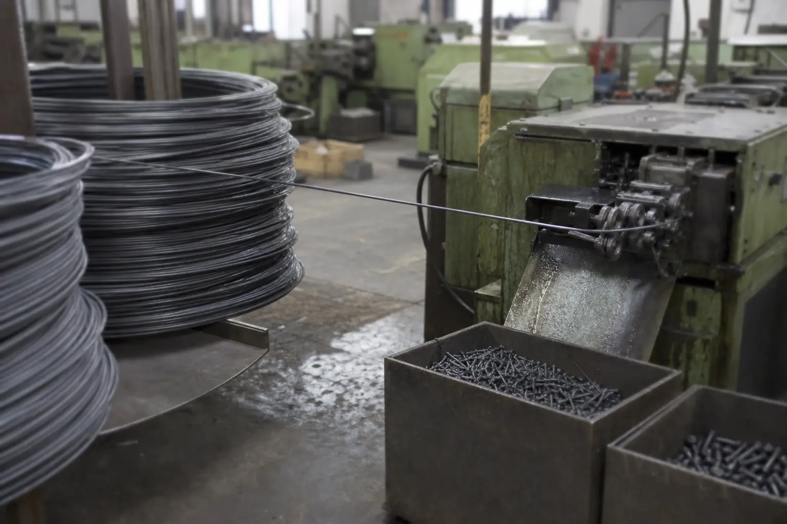
01 Cold heading
Wire rod is drawn to size and cold-formed into blanks. Forming rather than cutting keeps the grain flow continuous around the head, which is where a bolt is most likely to fail.
Head dimensions and under-head radius checked at set-up and per shift.
-
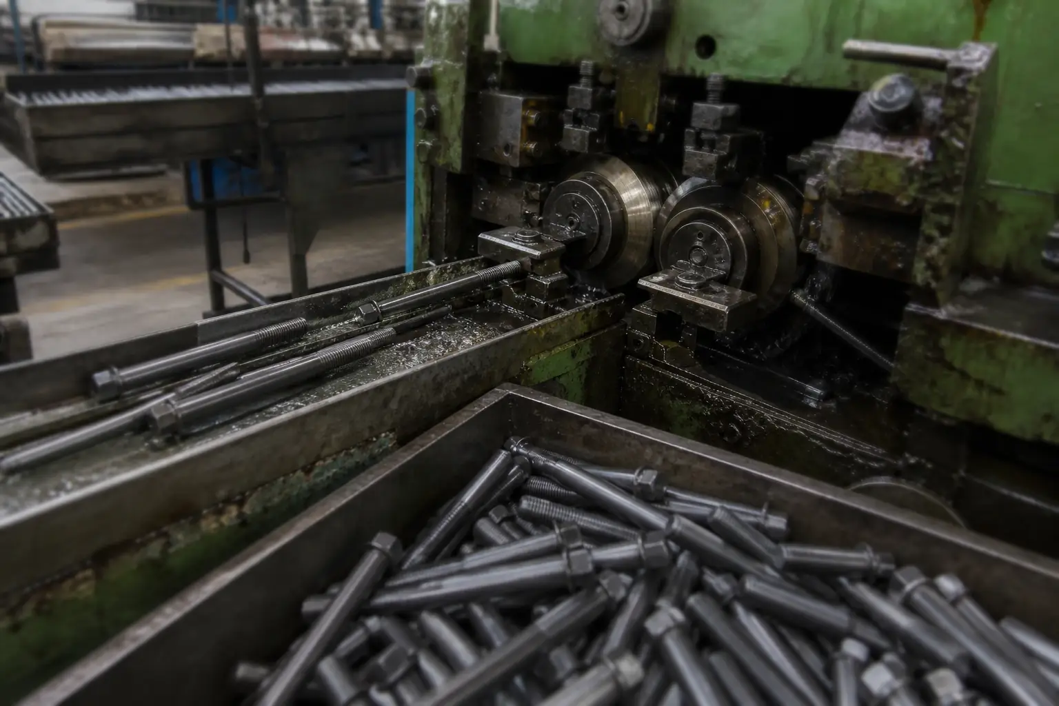
02 Thread rolling
Threads are rolled between hardened dies rather than cut. Rolled threads are stronger in fatigue than cut threads and hold pitch and flank angle far more consistently across a batch.
Go / no-go ring gauges to ISO 965 tolerance class 6g.
-
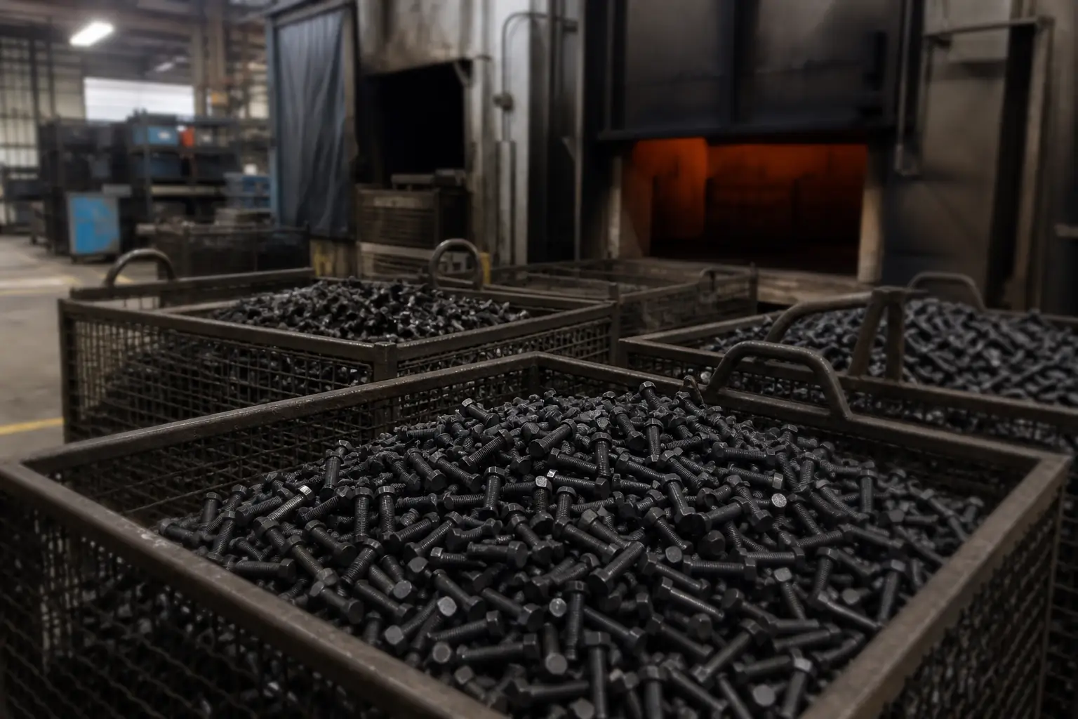
03 Heat treatment
Quench-and-temper brings carbon and alloy steel to the property class ordered — 8.8, 10.9 or 12.9 — with the furnace charge tracked so a finished lot can be traced back to it.
Core hardness and tensile tested per lot to ISO 898-1.
-
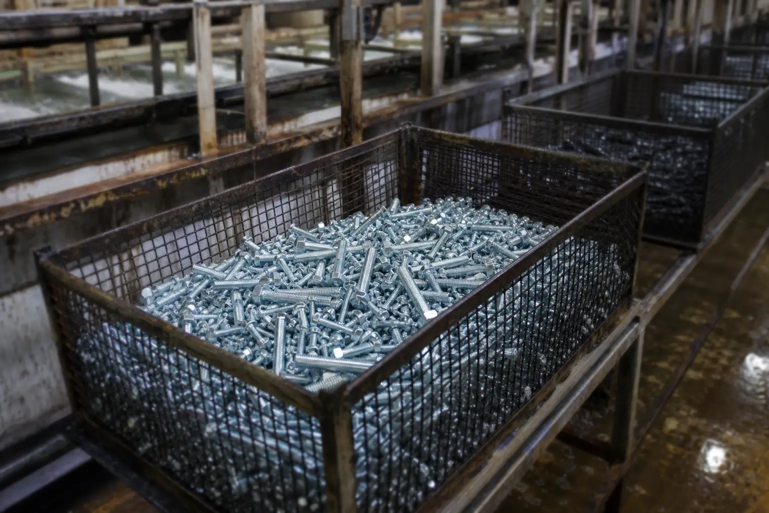
04 Surface treatment
Zinc, zinc-nickel, hot-dip galvanizing, black oxide, phosphate and Dacromet, selected against the service environment rather than against the price list.
Coating thickness and neutral salt spray hours to ISO 9227.