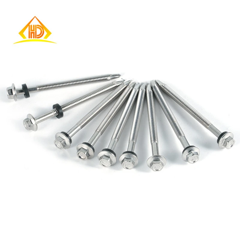
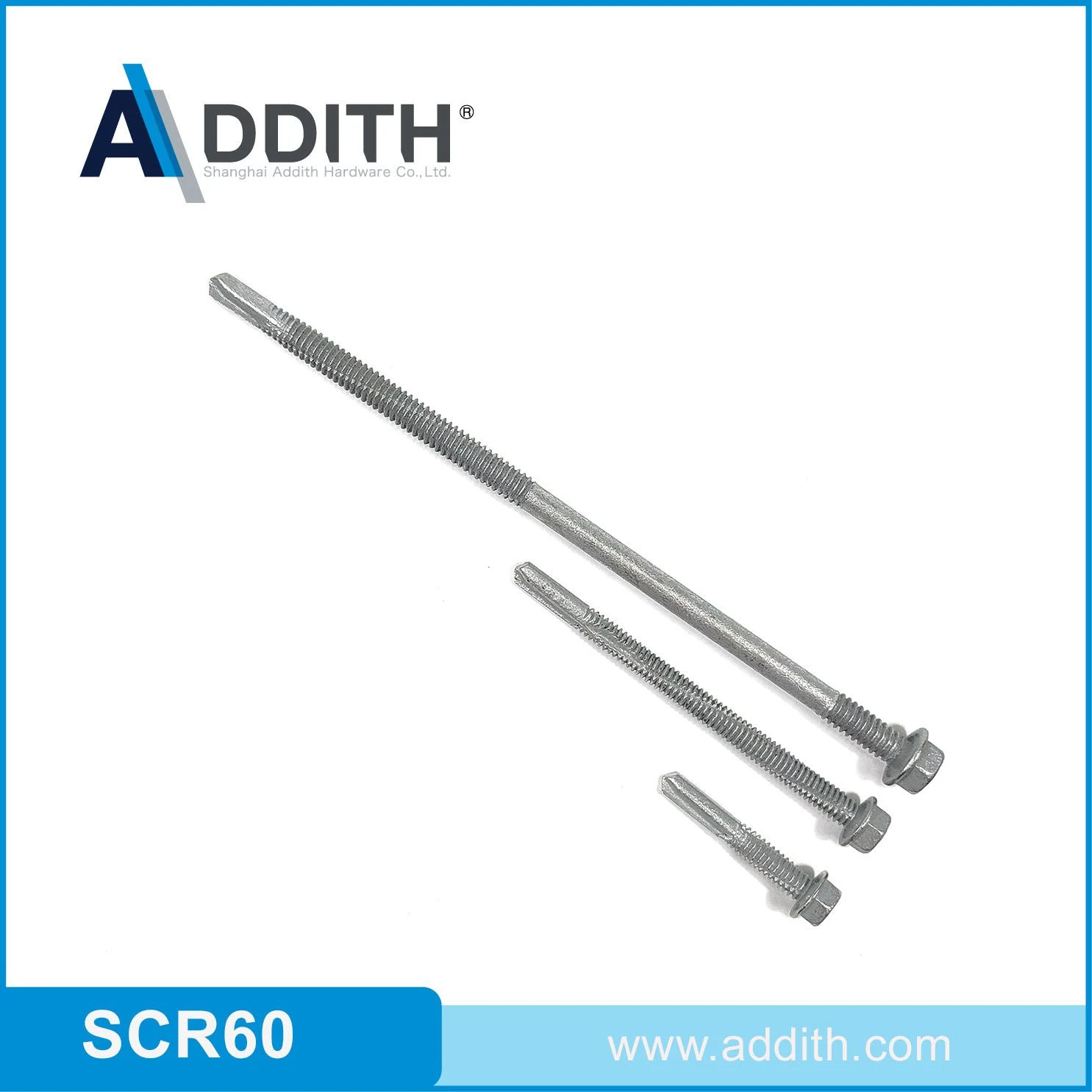
M3.5 Flow-Drilling Screws dimensions to Trade series (flow-drilling screws): coarse thread pitch 0.6 mm, clearance hole (ISO 273 medium) 3.9 mm, tapping drill 2.9 mm. Tighten to approximately 2 Nm at property class 8.8 in a dry, as-supplied condition.
- Coarse thread pitch
- 0.6 mm
- Clearance hole (ISO 273 medium)
- 3.9 mm
- Tapping drill
- 2.9 mm
- Tightening torque (class 8.8)
- 2 Nm
Figures are nominal values from the governing standard. Confirm against the tolerance class for your application before machining or ordering.
M3.5 Flow-Drilling Screws are manufactured to Trade series (flow-drilling screws) with a coarse thread pitch of 0.6 mm. This page lists the controlling dimensions for the M3.5 size — head geometry, width across flats, matching spanner size — together with the clearance hole, tapping drill and tightening torque used at assembly.
M3.5 Dimensional Row (Trade series (flow-drilling screws))
| Thread size | Clearance-hole diameter (mm) | Steel sheet range (mm) | Aluminum sheet range (mm) | Magnesium sheet range (mm) | Example drive / head |
|---|
| M3.5 | 4.3~4.8 | 0.3~1.8 | 0.8~5.0 | 0.8~3.5 | varies by series |
Spanner & Drive for M3.5 Flow-Drilling Screws
Drive geometry for M3.5 Flow-Drilling Screws is given by the row above; match the tool to the listed values.
Hole Sizes for M3.5
| Coarse-thread pitch (ISO 724) | 0.6 mm |
|---|
| Through-hole / clearance (ISO 273 medium) | 3.9 mm |
|---|
| Tapping drill, coarse thread | 2.9 mm |
|---|
Tightening Torque for M3.5
| Class 8.8 (dry, ~µ 0.125) | ≈ 2 Nm |
|---|
| Class 10.9 (dry, ~µ 0.125) | ≈ Nm |
|---|
| Class 12.9 (dry, ~µ 0.125) | ≈ 3.4 Nm |
|---|
Indicative dry-joint values. Lubrication can lower the required torque by 15–25%. Always confirm against the joint design, especially when going up a strength class.
Proof Load & Strength for M3.5
| Tensile stress area As (ISO 724) | 6.8 mm² |
|---|
| Proof load, class 8.8 | 3.9 kN |
|---|
| Proof load, class 12.9 | 6.6 kN |
|---|
| Min. ultimate tensile load, class 8.8 | 5.4 kN |
|---|
Proof load = tensile stress area × the proof stress Sp of the class, per ISO 898-1 — Sp is a lower figure than the yield stress Rp0.2 and the two are not interchangeable. The stress area is computed from this size's own diameter and pitch, so a fine-pitch designation gives the fine-pitch figure. Design the joint so the working preload stays below the proof load of the class selected.
Installation Tips for M3.5 Flow-Drilling Screws
- At M3.5 the joint is sensitive to over-torque — use a torque-limiting driver and check the head doesn't bury into a softer counterpart.
Mating Parts for M3.5
For M3.5, pair with a M3.5 hex nut (ISO 4032 / DIN 934) and, where used, a M3.5 flat washer (ISO 7089 / DIN 125A) under the head and under the nut.
Custom manufacturing · Made to drawing
Need flow-drilling screws in a size this table does not list?
This page covers M3.5 flow-drilling screws. Thread size and pitch, length, property class, drive form, head geometry and head marking are all specifiable — the standard part is where it starts, not where it stops. Made by cold heading or warm forging.
Minimum order from 2,000 pieces; samples within 7 days of drawing approval.
Custom screw manufacturingSend a drawing
Applications & Industries for M3.5 Flow-Drilling Screws
What Flow-Drilling Screws are specified for, industry by industry. Stocked from M3 to M6.
Industries that specify Flow-Drilling Screws
-
Magnesium housings
One-side fastening avoids a loose nut inside a closed section.
-
Industrial panels
The clearance and sheet ranges define the process window.
-
Automotive body structures
Flow-drilling screws create a threaded boss through one-side sheet access.
-
Aluminum fabrication
The process joins aluminum sheet without a separate pre-drilled thread.
-
Machine building & OEM
The default fastener on production equipment: covers, brackets, motor mounts and sub-assemblies tightened to a specified torque.
-
Automotive & transport
Chassis, driveline and body fixings that see vibration and are assembled to a controlled preload.
Typical applications
- selecting the process for the sheet thickness
- using the specified drive and head for the assembly tool
- flow-drilling a thread into steel, aluminum or magnesium
- matching the clearance-hole range to the screw size
- assemblies that are dismantled for service and re-torqued
- joints where the property class is stated on the drawing
Service conditions to specify against
- Marine and coastal
- Available in A4 (316) stainless for chloride exposure — coastal structures, pool halls, water treatment and deck hardware, where A2 will eventually pit.
- High load
- Supplied in ISO 898-1 property classes, so the joint can be designed to a stated proof load and tightened to a calculated torque rather than by feel.
- Torque and preload
- The joint is designed around bolt tension, so lubrication, coating and the friction coefficient all change the torque figure — state them together.
Where to use something else
- Do not use a flow-drilling screw outside its material or sheet-thickness window; heat and thread formation are process-dependent.
- Do not use a machine thread into unthreaded sheet or timber; use a tapping screw, rivet nut or insert made for that parent material.
Full application guide: where Flow-Drilling Screws are used, how to specify them, and the cases they are wrong for