
Dimensional data for M36 Nyloc Lock Nuts to DIN 985 / ISO 7040, with the drive and the installation notes for this type.
Values are taken from the governing standard rather than from a general machine-thread table, because this type is not selected on one.
M36 Dimensional Row (DIN 985 / ISO 7040)
| Size | Pitch (mm) | Width across flats s (mm) | Width across corners e min (mm) | Total height m (mm) | Metal height (mm) | Reference standard | Notes |
|---|---|---|---|---|---|---|---|
| M36 | 4.0 | 55.0 | 60.79 | 29.0 | 29.0 | DIN 985 / ISO 7040 | With nylon insert, single use |
Spanner & Drive for M36 Nyloc Lock Nuts
Drive geometry for M36 Nyloc Lock Nuts is given by the row above; match the tool to the listed values.
Tightening Torque for M36
| Class 8.8 (dry, ~µ 0.125) | ≈ 2523 Nm |
|---|---|
| Class 10.9 (dry, ~µ 0.125) | ≈ 3593 Nm |
| Class 12.9 (dry, ~µ 0.125) | ≈ 4204 Nm |
Indicative dry-joint values. Lubrication can lower the required torque by 15–25%. Always confirm against the joint design, especially when going up a strength class.
Proof Load & Strength for M36
Nuts are graded to ISO 898-2 by the proof load the nut itself will hold (classes 04, 05, 5, 6, 8, 10 and 12), not by the 8.8 / 10.9 / 12.9 scale used for bolts. A class-8 nut is the correct mate for a class-8.8 bolt, and the joint is designed on the bolt, so no bolt-tension figure is quoted here.
Installation Tips for M36 Nyloc Lock Nuts
- At M36 the stretch in the bolt becomes the controlling factor — for critical joints, use angle-controlled or stretch-controlled tightening instead of pure torque.
Mating Parts for M36
Pair M36 with the matching M36 bolt or screw, plus a M36 flat washer where required to distribute load on softer materials.
Custom manufacturing · Made to drawing
Need nyloc lock nuts in a size this table does not list?
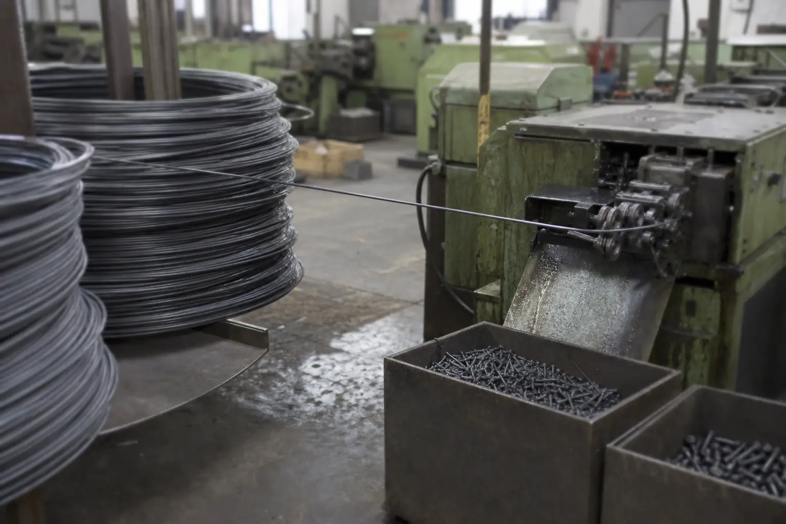
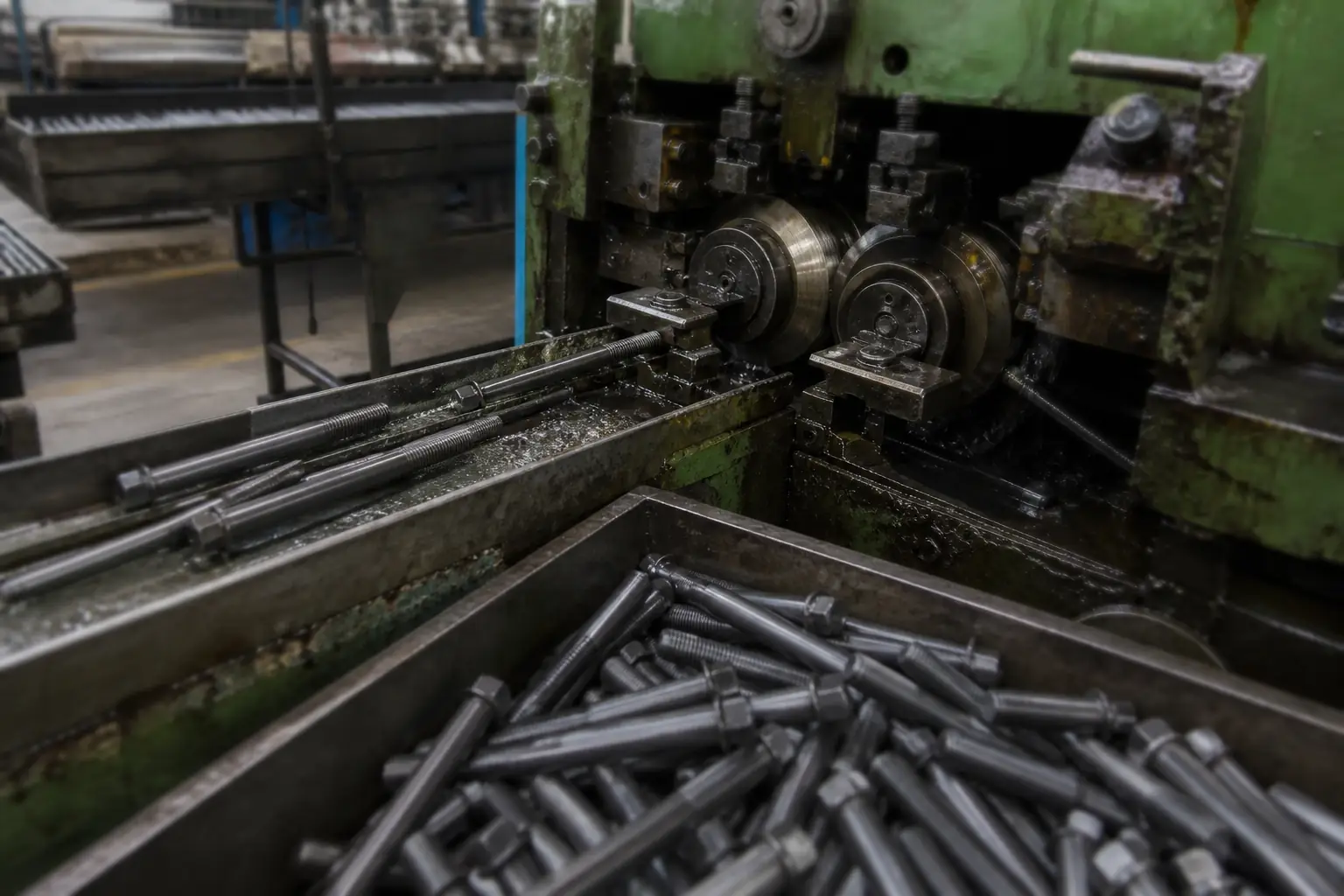
This page covers M36 nyloc lock nuts. Thread, height, across-flats, property class, locking feature and flange form can all be varied, including thread sizes the standard series does not run to. Made by cold heading or tapping.
Minimum order from 2,000 pieces; samples within 7 days of drawing approval.